Abstract
In many animals, blood cell production occurs in the bone marrow. Hematopoiesis is complex, requiring self-renewing and pluripotent stem cells, differentiated progenitor and precursor cells, and supportive stroma, adipose tissue, vascular structures, and extracellular matrix. Although imaging is a vital tool in hematology research, the 3-dimensional architecture of the bone marrow tissue in situ remains largely uncharacterized. The major hindrance to imaging the intact marrow is the surrounding bone structures are almost impossible to cut/image through. We have overcome these obstacles and describe a method whereby whole-mounts of bone marrow tissue were immunostained and imaged in 3 dimensions by confocal fluorescence and reflection microscopy. We have successfully mapped by multicolor immunofluorescence the localization pattern of as many as 4 cell features simultaneously over large tiled views and to depths of approximately 150 μm. Three-dimensional images can be assessed qualitatively and quantitatively to appreciate the distribution of cell types and their interrelationships, with minimal perturbations of the tissue. We demonstrate its application to normal mouse and human marrow, to murine models of marrow failure, and to patients with aplastic anemia, myeloid, and lymphoid cell malignancies. The technique should be generally adaptable for basic laboratory investigation and for clinical diagnosis of hematologic diseases.
Introduction
The bone marrow (BM) is the organ responsible for blood cell production in mammals and many other higher organisms. The marrow occupies the bone interior and constitutes 4% to 5% of total body weight in humans. Although anatomically complex, with the many various types of cells highly organized in a meshwork of capillary-venous sinuses and surrounding extracellular matrix,1-4 only recently the hematopoietic microenvironment was described; localization of differentiated elements, as in erythropoietic islands and lymphocyte nodules were defined; and stem cell niches' cellular components were appreciated.5-7 Nevertheless, the 3-dimensional (3D) architecture of the BM in situ remains elusive, limited mainly by the necessity to remove hematopoietic elements from their boney enclosure and to work in the 2 dimensions of a conventional microscope slide. Furthermore, current methods for BM visualization have inherent disadvantages, including loss of tissue integrity (eg, shrinkage or shape distortion), loss of antigenicity due to decalcification processing and sectioning procedures, and the limitation of insufficient volume with typical tissue sections.
Confocal laser scanning microscopy (CLSM) is a technique widely used in many fields producing high spatial resolution and detailed information along x-, y-, and z-axes, allowing optical sectioning of objects.8,9 Computer-generated 3D reconstructions of organs and tissues enable visualization of cells and cellular networks in situ and provide insights into the anatomical and functional relationships of microscopic structures. CLSM has been successfully used on whole-mount immunostained preparations of various organs, tissues, cells, and embryos of a variety of species.10-14
The aim of the current study was to develop a new method to visualize BM architecture, using confocal microscopy of multiple antibody (Ab)–labeled whole-mount preparations. We provide, to our best knowledge, the first confocal images of BM generated by such a methodology. The technique was evaluated in experiments with mouse and human tissues. Potential applications were explored with robust 3D rendering of images of normal, manipulated, and diseased BM, including noninvasive quantitative measurements of cell distribution. BM whole-mount, multicolored immunostaining followed by confocal 3D visualization should be applicable to clinically laboratory experiments and to the examination of clinical BM specimens in blood diseases.
Methods
Antibodies
The staining sequences are summarized in supplemental Table 1 (available on the Blood Web site; see the Supplemental Materials link at the top of the online article). Primary and secondary antibodies are listed in supplemental Tables 2 and 3.
AA mice and BM-transplanted mice
Inbred B6, congenic C.B10, and transgenic B6/EGFP mice were from The Jackson Laboratory. All mice were bred and maintained at the National Institutes of Health animal facility under standard care. Male and female mice were used at 6 to 16 weeks of age. All animal study protocols were approved by the National Heart, Lung, and Blood Institute Animal Care and Use Committee.
Aplastic anemia (AA) mice were generated as previously described.15,16 The B6/EGFP transgenic mice carry an enhanced green fluorescent protein (EGFP) cDNA under the control of a chicken β-actin promoter and a cytomegalovirus enhancer in all of the tissues, except for erythrocytes and hair. Two types of BM cell–transplanted mice were generated using the B6/EGFP mice. Either total BM cells were extracted from tibiae and femurs as previously described,17 or to obtain lineage (Lin)− stem cell antigen 1 (SCA1)+cKit+ cells (known as LSK cells) (an enriched population of hematopoietic stem cells [HSCs]), total BM cells were stained with phycoerythrin (PE)–Cy5-anti-Sca1, allophycocyanin (APC)–anti-cKit, and PE-conjugated lineage antibodies for CD3e, CD4, CD8a, CD11b, CD45R, Gr-1, and TER-119 for 30 minutes at 4°C, and sorted using the FACSVantage cell sorter (BD Biosciences), as lineage-negative, Sca1 and cKit double-positive LSK population. Total BM cells (1 × 10⁷/mouse) or LSK cells (1 × 10⁴/mouse) were infused into 11 Gy total-body irradiation preirradiated B6 recipients to generate total BM–transplanted (BMT) (B6/tBM/EGFP) and LSK cell–transplanted (B6/LSK/EGFP) mice, respectively which were analyzed at days 1, 7, 14, and 28 after cell transplantation.
Healthy human donors and patients
Human BM specimens were collected from healthy donors or patients with written informed consent for testing, according to protocols approved by the Institutional Review Board of the National Heart, Lung, and Blood Institute. Patient and disease characteristics are provided in supplemental Table 4.
Cellular composition analyses in AA or AIM mice
Peripheral blood cell counts of AA mice were obtained using the Hemavet 1700 analyzer (Drew Scientific). BM cells extracted from tibiae and femurs of AA or BMT mice were stained with PE–anti-CD8a Ab and examined by the FACSAria II Flow Cytometer (BD Biosciences).
Immunofluorescence labeling protocols for whole-mounts
Mouse or human BM tissues were obtained from sternums from necropsies or from core biopsies of the posterior iliac crests, respectively. BM tissues were transected to obtain 2- to 3-mm fragments, fixed, and stained as whole-mounts without further sectioning. Specimens were fixed with 150 μL of 4% paraformaldehyde (PFA) in phosphate-buffered saline (PBS) in a 96-well plate at room temperature (RT) for 20 minutes (mouse) or 60 minutes (human). After washing with PBS (3 × 15 minutes), specimens were immediately subjected to staining procedures.
First BM tissues were incubated with anti-CD16/32 Ab (mouse Fc-block; 1:40 dilution; BD Pharmingen) or human AB blood type serum (1:40 dilution) for mouse and human samples, respectively, at RT, for 45 minutes, to block nonspecific Ab binding. All subsequent incubations were performed using 160-μL volume of solutions (staining, washing, or blocking) by rotating gently on the Belly Dancer (Stovall). Preliminary experiments using single labels were performed to assess the suitability of various antibodies and to determine optimal incubation conditions. We found that simultaneous incubation with 2 primary antibodies, even of different isotypes, resulted in cross-binding and prevented detection of one of the cellular epitopes. We overcame this problem by using a combination of up to 3 sequential immunolabeling steps: (1) unconjugated primary antibodies: specimens were incubated with the primary antibodies (1:40 dilution) at 4°C overnight, washed with PBS (3 × 15 minutes), then incubated with fluorescently labeled F(ab′)2 fragments as secondary antibodies (1:60 dilution) at RT for 45 minutes; after washing, nonspecific binding was blocked by incubation with normal immunoglobulin G of the same species and isotype as the primary antibodies (1:40 dilution) at RT for 45 minutes; (2) biotin-conjugated primary antibodies: specimens were incubated with biotinylated-primary antibodies (1:40 dilution) at 4°C overnight, washed, and incubated with RhoRX-, TxRed-, or APC-conjugated streptavidin (1:60 dilution) at RT for 45 minutes; after washing, specimens were subjected to similar blocking as described; (3) fluorescently conjugated primary antibodies: specimens were incubated with the directly conjugated primary antibodies (1:40 dilution) at 4°C overnight and washed. Additional stains used were BODIPY 493/503 (Invitrogen), 1:500 dilution at RT for 20 minutes for adipocytes (lipid droplets),18 and DAPI (4′,6-diamidino-2-phenylindole; Invitrogen) for nuclei.
Specimens from the EGFP mice were processed through the same procedure, but without fixation due to severe reduction of EGFP signals after exposure to formaldehyde and without rotation due to the fragility of the tissues. Nuclei were stained using Hoechst 33342 (Calbiochem) 1:500 dilution at 37°C for 20 minutes.
Confocal fluorescence and reflection imaging
All images were acquired by CLSM with Zeiss LSM 510 and LSM 710 confocal systems (Carl Zeiss MicroImaging). The fluorescently labeled BM tissue within bone fossae was placed cut-face down onto a 35-mm coverglass culture dish (MatTek Corporation), in (50-100 μL) PBS to prevent tissue desiccation. The BM tissue beneath the bone edge was located and positioned using differential interference contrast (DIC) illumination. Fluorescence images of as many as 4 colors were captured sequentially, using a 360-nm or 405-nm laser line and emission 385 to 470 nm for DAPI/Hoechst, a 488-nm laser line and emission between 505 and 550 nm for fluorescein isothiocyanate/EGFP and DIC, a 561-nm laser line and emission between 575 and 615 nm for RhoRX/TxRed, and a 633-nm laser line and emission over 640 nm for Cy5/APC. Series of x-y-z images of typically 640 × 640 μm2 x-y size were collected along the z-axis at 1- to 4-μm intervals to approximately 100- to 150-μm depths throughout the BM tissue, using 10× and 20× NA 0.75 objectives. To image thick samples, we used a Zeiss AIM 4.0 software feature that modulates laser power and detector sensitivity with the depth of imaging, automatically correcting for the depth of the focal plane. To assess cellular localization, images were also taken using a 40× C-Apochromat, NA = 1.2 water-immersion objective. In addition, we used confocal reflection microscopy to visualize the bone. Reflection was captured by placing in the beamsplitter an NT 80/20 dichroic light-splitter using 6% of 633-nm laser light and allowing reflected light to directly enter the collection channel. On the same sample, fluorescence was sequentially captured by standard confocal methodology, as described above, and combined with reflection imaging. Identical thickness optical sections were collected along the z-axis for both reflection and fluorescence imaging. In some circumstances, large regions were scanned using the tile function of the software to generate stitched volumes comprising approximately 2.5 × 1.2 mm2 (x-y) and 150 μm (z).
Reconstruction of 3D volumes and analysis
The volume data were used to create 3D renderings of the BM architecture using Imaris software 6.4 and 7.1 (Bitplane). This software provides multiple means to inspect the 3D arrangements of various cell types and other components of native tissue at various angles in x-y-z space as well as 3D rotation movies, attached as supplemental material. Occasionally, confocal images were pseudocolored.
For quantitative assessment of the 3D cell distributions, z-stacks were further processed using the Imaris XT module which integrates MATLAB applications (Version 710; MathWorks). The BM specimens (a typical volume of 600 × 600 × 100 μm3) were examined regarding cell numbers, positions, and relationships to each other by distance measurements. Statistics were exported in Microsoft Office 2007 Excel software. In addition, cell clustering was assessed by neighboring distributions (cells within a centroid to centriod distance < 25 μm in the 3D space) using the open source PicViewer software as previously described (J. Dempster, University of Strathclyde; http://spider.science.strath.ac.uk/sipbs/software_imaging.htm). Experimental data were compared with the Monte Carlo simulation of randomly distributed cells of equal density.19,20 Statistical analysis of the neighboring distribution of cells was carried out by the Mann-Whitney U test using SigmaStat 3.1 software (Systat Software). Composite figures were assembled with Adobe Photoshop 7.1 software (Adobe Systems).
Results
Overview of confocal microscopy analysis of BM whole-mount specimens
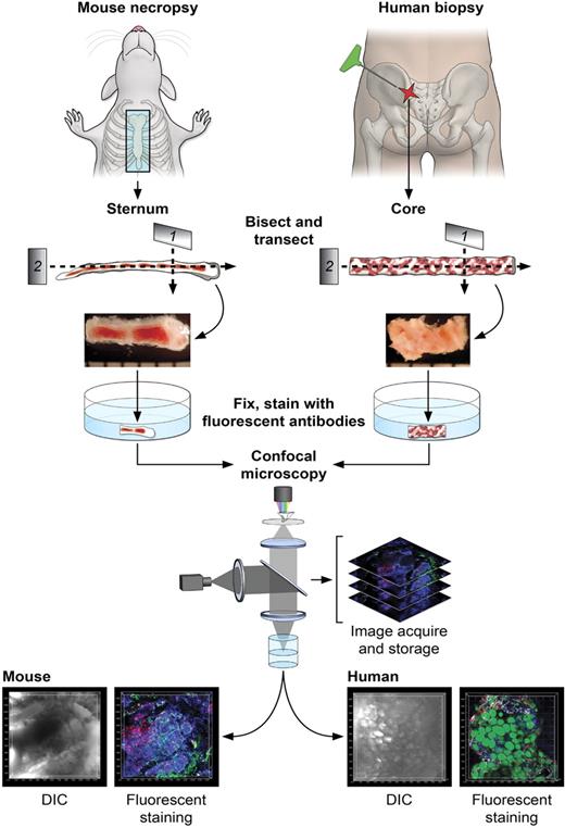
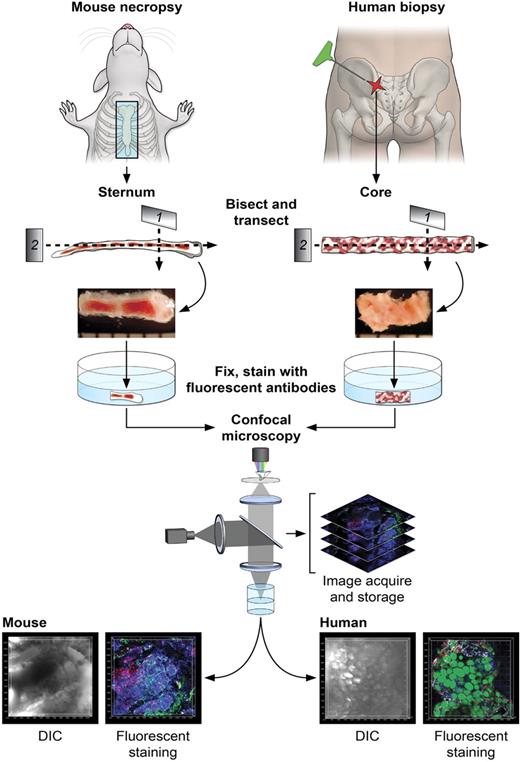
Figure 1 illustrates the steps in the sample preparation and performance of confocal microscopy. For the mouse, BM was obtained from freshly killed animals by removal and then bisection in the sagittal plane of the sternum (supplemental Video 1). For human BM, a biopsy core was extracted from the posterior iliac crest of healthy volunteers or patients and similarly transversely transected. Whole-mount tissue fragments were placed in 96-well plates, fixed, stained using immunofluorescently labeled antibodies and other dyes, and subjected to confocal microscopy. Captured stacks of DIC and multicolor fluorescence images were imported in Imaris software for 3D reconstructions and quantitative analyses. Multiple preliminary experiments were required to empirically establish optimal fixation and immunolabeling conditions for mouse and human BM tissues. Of importance, autofluorescence of bone marrow tissue, unfixed or PFA-fixed, was extremely low (supplemental Figure 2A-B) and did not influence imaging or subsequent analyses. Control experiments using isoptype-specific antibodies demonstrated the specificity of immunofluorescence (supplemental Figure 2C-D). Although quantitative analyses of various cells' frequencies performed computationally on microscopy images has the clear advantage of noninvasive enumeration of cells in situ, we performed for comparison parallel flow cytometric analyses on preserved samples (supplemental Table 5) and cell counting using routine (enzyme-based) immunocytochemistry of BM sections (data not shown). Excellent correlations of results were present for mouse sterna, and discrepancies in human samples were expected (see “Normal human BM and BM of patients with hematologic diseases”).21
Diagrams of the protocol of BM sample preparation and confocal microscopy. For mouse BM, sternums were bisected sagittally into 2 to 3 segments. For human BM, core biopsies were bisected into segments (2-4 mm). Segments were further transected, fixed (except for EGFP-expressing tissues), and fluorescently stained as whole-mounts. Fluorescently labeled BM tissues were subjected to confocal microscopy, and series of images were used to reconstruct the 3D architecture of BM (related images in supplemental Video 1).
Diagrams of the protocol of BM sample preparation and confocal microscopy. For mouse BM, sternums were bisected sagittally into 2 to 3 segments. For human BM, core biopsies were bisected into segments (2-4 mm). Segments were further transected, fixed (except for EGFP-expressing tissues), and fluorescently stained as whole-mounts. Fluorescently labeled BM tissues were subjected to confocal microscopy, and series of images were used to reconstruct the 3D architecture of BM (related images in supplemental Video 1).
Architecture of BM from the normal mouse
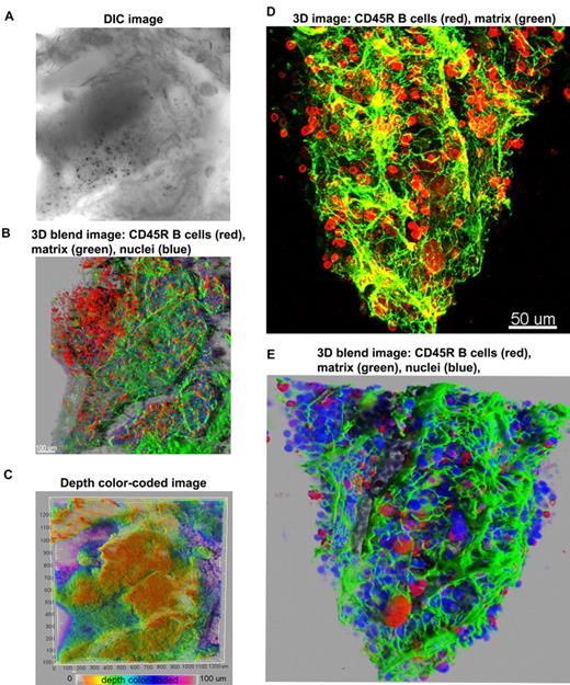
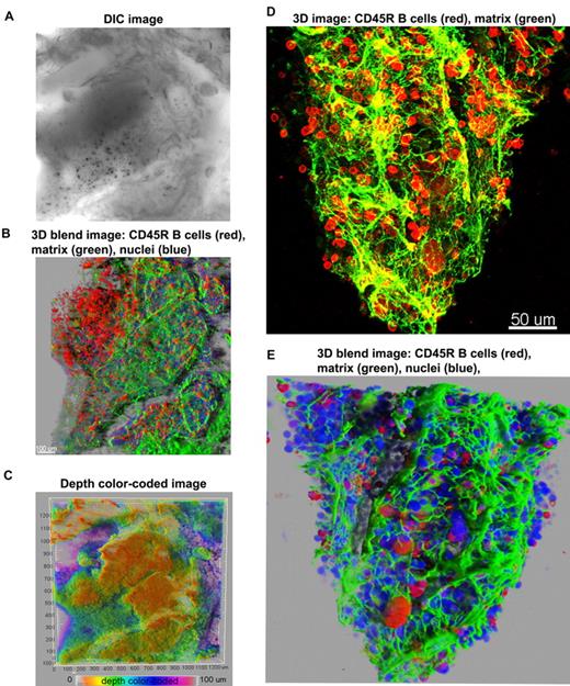
First, we used antibodies to a B-cell marker (CD45R; B cells compose approximately 30% of marrow hematopoietic cells), and to perlecan, an extracellular matrix component, allowing visualization of the structural framework in which hematopoiesis develops. Figure 2 illustrates 3D confocal images of cells within a bone cavity. The meshwork of trabecular bone and spiculae, within which the hematopoietic tissue and stroma are suspended, can be inspected in a DIC image (Figure 2A and supplemental Figure 3). Figure 2 displays 2 different ways of 3D reconstruction, the 3D blend image and the maximum intensity projections. The 2 modalities used to render 3D images are complementary. The maximum intensity projection (MIP) is most often used to illustrate 3D data in confocal microscopy because images are obtained with facility, but the depth dimensions of the data are difficult to perceive in a flat 2-dimensional MIP image. To assist visualization, 3D rotation movies using MIP images help visualize spatial relationships in the volume data. Sometimes depth dimension can be color coded, as we have also illustrated, but color coding can be difficult to perceive in 3- to 4-channel data. The blend projection allows better perception of 3D space, even from a flat 2-dimensional image, enabling changes in the opacity/transparency of different channels and providing “transparency” for some objects. Software algorithms used in the blend projection will display in the first (front) layers the objects closer to the viewer, and subsequent layers are built behind to provide better perspective. In addition, this projection allows shining external light sources on the image and 3-dimensionality from light and shadow effects. Blend projections are much more laborious to obtain and 3D rotation movies are not easily generated from them.
Overview of 3D reconstructions of mouse BM architecture. Using DIC (A), mouse marrow tissue within the bone fossae of the sternum was located and examined; corresponding z-series of immunofluorescence images (B) (approximate volume of 600 × 600 × 150 μm3) were reconstructed. (B) A 3D blend rendering showing large islands of CD45R+ cells (B lymphocytes in red), surrounded by extracellular matrix (perlecan in green), and DAPI (blue) identifying all nucleated cells. (C) A depth color coded 3D image where the depth was pseudocolored (0 μm = orange and 100 = magenta) of the same field as in panels A and B. The close-up 3D images either as maximum intensity (D) or as blend projection (E) display an intricate network of extracellular matrix (perlecan in green) outlining blood vessels and the nests of CD45R+ cells (B lymphocytes in red). DAPI (blue) identifies all nucleated cells (E). Related images appear in supplemental Video 2.
Overview of 3D reconstructions of mouse BM architecture. Using DIC (A), mouse marrow tissue within the bone fossae of the sternum was located and examined; corresponding z-series of immunofluorescence images (B) (approximate volume of 600 × 600 × 150 μm3) were reconstructed. (B) A 3D blend rendering showing large islands of CD45R+ cells (B lymphocytes in red), surrounded by extracellular matrix (perlecan in green), and DAPI (blue) identifying all nucleated cells. (C) A depth color coded 3D image where the depth was pseudocolored (0 μm = orange and 100 = magenta) of the same field as in panels A and B. The close-up 3D images either as maximum intensity (D) or as blend projection (E) display an intricate network of extracellular matrix (perlecan in green) outlining blood vessels and the nests of CD45R+ cells (B lymphocytes in red). DAPI (blue) identifies all nucleated cells (E). Related images appear in supplemental Video 2.
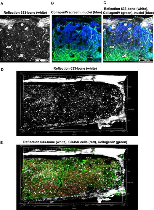
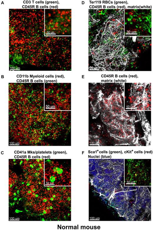
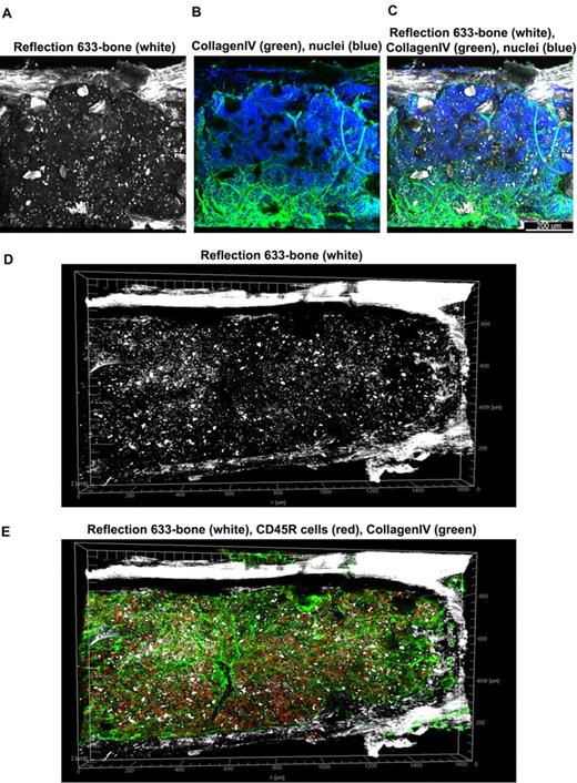
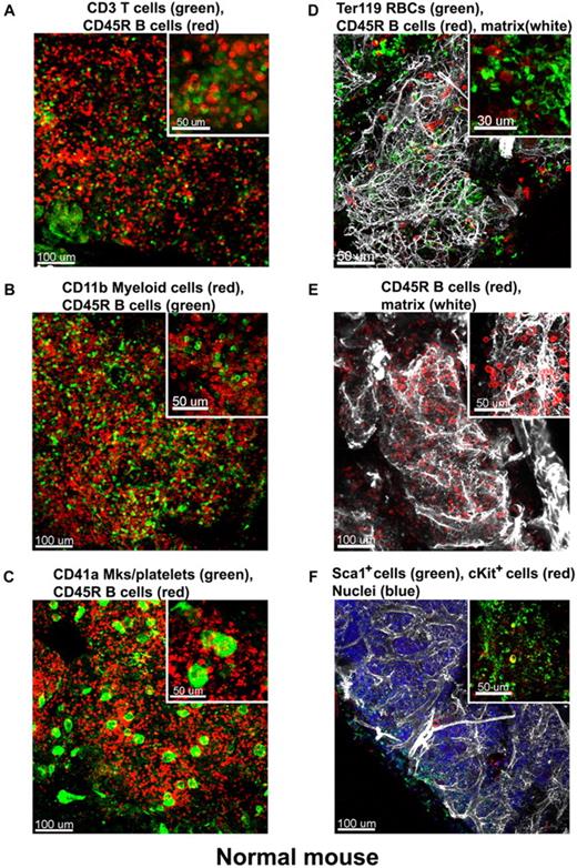
At low magnification of the fluorescent images, the tissue appears compartmentalized: multiple islands of hematopoietic cells can be visualized surrounded by a network of extracellular matrix which connects adjacent islands (Figure 2B). Topographical 3D images of the cellular compartments can be obtained by color coding the depth of the volume, as displayed in Figure 2C. When inspected at higher magnification, the extracellular matrix forms intricate networks in which B lymphocytes lie (Figure 2D-E and supplemental Video 2). Because perlecan is a component of basement membranes, it reveals also the arterioles and venules that supply and drain intratrabecular spaces. To more clearly assess relationships between bone structure, extracellular matrix, blood vessels, and cells, we combined confocal reflection and fluorescence microscopy (Figure 3 and supplemental Video 3). We introduced a novel technique to image bone, confocal reflection (Figure 3A), to clearly visualize the outer bone edge as well as bone trabecullae and spines within the cavity. Reflection of 633-nm laser light allowed capture of images of the surface of the bone as well as inner structures to depths of 180 μm without deterioration of resolution and image quality. Spaces occupied by bone appeared as “holes,” discontinuities in the corresponding fluorescence image displaying the BM cells (DAPI) and extracellular matrix (collagen type IV; Figure 3B) overlapping completely in the merged image (Figure 3C). We used this method to collect tiled z-stacks of images over large regions (2.6 × 1.2 mm2 in x-y and 150 μm in depth), which enabled exploration at high resolution of a very large volume of tissue (Figure 3D-E). We next performed a series of double-labeling experiments, with various combinations of 2 different lineage-specific antibodies for T and B cells, myeloid cells, megakaryocytes/platelets, and erythrocytes, which are illustrated in Figure 4A through D. These images depict a heterogeneous mixture of the main lineage cells. T cells (Figure 4A and supplemental Video 4) are low in number (∼ 2.5%), similar to flow cytometry results, and scattered throughout the intertrabecular space. In contrast, much more numerous (∼ 26%) myeloid cells (Figure 4B) are present adjacent to bone trabeculae. Megakaryocytes and platelets (Figure 4C and supplemental Video 5) are detected as large and small green cells, respectively, as the anti-CD41 antibodies bound equivalently to both. Megakaryocytes (∼ 2%) appear scattered and singly and evenly distributed. Similar observations have been made in vivo using CD41-EYFP mouse models.22 Erythroid precursors (∼ 31%) form small clusters that are dispersed throughout the intertrabecular space (Figure 4D). B cells appear in clusters, surrounded by a meshwork of extracellular matrix and microvessels extending from the bone edge (Figure 4E). Sca1 and cKit are expressed (nonexclusively) on murine HSCs and hematopoietic progenitor cells (HPCs); in many studies, mouse HSCs are identified as Sca1+cKit+ but as not binding to lineage-specific antibodies. By confocal microscopy, fluorescein isothiocyanate–labeled Sca1+ cells, rhodamine Red-X (Rho)–labeled cKit+ cells, and double positive cells are visualized at the expected extremely low frequency (0.1%; Figure 4F) similar to flow cytometry. In the murine tissue, adipocytes were absent from the hematopoietic cell–rich spaces.
Tiled views of confocal reflection and fluorescence of the normal mouse BM. Confocal reflection 3D image (A) displays the bone structure (white): the outer shell as well as several internal bone spikes and trabecullae can be identified (using a 633-nm laser light reflected on the imaging detector). In the corresponding confocal fluorescence 3D image (B), cells (DAPI, blue) and vascular structures and extracellular matrix (collagen type IV, green) are shown; several tissue discontinuities appear like “holes.” The merged image (C) clearly demonstrates the overlap of the bone structures over these discontinuities. Tiled z-stacks of images were collected over large volume (2.6 × 1.2 mm × 150 μm) of the mouse BM tissue and computationally stitched. A large tile over entire bone fossae is depicted in panels (D) (bone reflection) and E (merged with the fluorescence of CD34 in red, collagen type IV in green, DAPI in blue) respectively, to illustrate very good tissue preservation. Related images appear in supplemental Video 3).
Tiled views of confocal reflection and fluorescence of the normal mouse BM. Confocal reflection 3D image (A) displays the bone structure (white): the outer shell as well as several internal bone spikes and trabecullae can be identified (using a 633-nm laser light reflected on the imaging detector). In the corresponding confocal fluorescence 3D image (B), cells (DAPI, blue) and vascular structures and extracellular matrix (collagen type IV, green) are shown; several tissue discontinuities appear like “holes.” The merged image (C) clearly demonstrates the overlap of the bone structures over these discontinuities. Tiled z-stacks of images were collected over large volume (2.6 × 1.2 mm × 150 μm) of the mouse BM tissue and computationally stitched. A large tile over entire bone fossae is depicted in panels (D) (bone reflection) and E (merged with the fluorescence of CD34 in red, collagen type IV in green, DAPI in blue) respectively, to illustrate very good tissue preservation. Related images appear in supplemental Video 3).
Immunostaining of the normal mouse BM. Mouse BM whole-mount specimens were fluorescently double labeled with various combinations of lineage-specific antibodies for T and B cells, myeloid cells, megakaryocytes/platelets, and erythrocytes. In addition extracellular matrix was also visualized by perlecan staining. Each inset shows a higher magnification of a 100-μm2 area of the corresponding confocal image, these depict a heterogeneous mixture of the main lineage cells: (A) CD3e+ T cells (green) appear scattered and much less numerous than CD45R+ B cells (red). (B) In contrast, CD11b+myeloid cells (red) are more abundant than B cells (green). (C) Megakaryocytes (large cells) and small platelets, both CD41+ (green), appear scattered evenly in the intertrabecullar space. (D) TER119+erythroid cells (green) are numerous and tend to form clusters. (E) CD45R+ B cells (red) are abundant and appear in close proximity to the extracellular matrix network (perlecan, white). (F) Hematopoietic stem and progenitor cells identified as double-labeled Sca1+ and cKit+ are scarce. A complex network of extracellular matrix surrounds and supports the cellular compartments (white in panels D-E). Scale bars are in micrometers. All results are representative of at least 3 independent experiments. Related images appear in supplemental Videos 4 and 5.
Immunostaining of the normal mouse BM. Mouse BM whole-mount specimens were fluorescently double labeled with various combinations of lineage-specific antibodies for T and B cells, myeloid cells, megakaryocytes/platelets, and erythrocytes. In addition extracellular matrix was also visualized by perlecan staining. Each inset shows a higher magnification of a 100-μm2 area of the corresponding confocal image, these depict a heterogeneous mixture of the main lineage cells: (A) CD3e+ T cells (green) appear scattered and much less numerous than CD45R+ B cells (red). (B) In contrast, CD11b+myeloid cells (red) are more abundant than B cells (green). (C) Megakaryocytes (large cells) and small platelets, both CD41+ (green), appear scattered evenly in the intertrabecullar space. (D) TER119+erythroid cells (green) are numerous and tend to form clusters. (E) CD45R+ B cells (red) are abundant and appear in close proximity to the extracellular matrix network (perlecan, white). (F) Hematopoietic stem and progenitor cells identified as double-labeled Sca1+ and cKit+ are scarce. A complex network of extracellular matrix surrounds and supports the cellular compartments (white in panels D-E). Scale bars are in micrometers. All results are representative of at least 3 independent experiments. Related images appear in supplemental Videos 4 and 5.
Architecture of severely damaged BM tissues of AA mice
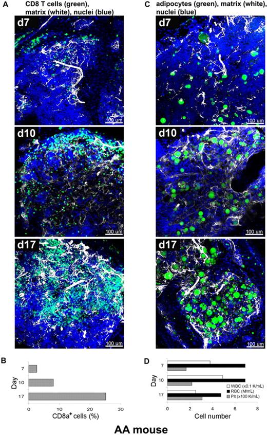
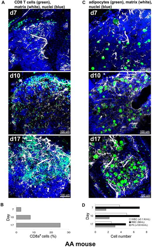
We next applied the staining procedure to murine immune-mediated AA, a model that has been developed in our laboratory, to relate the kinetics of marrow destruction by reactive T cells to a pathologic BM architecture.15,16 In current experiments, BM of recipient animals was obtained at days 7, 10, and 17, and labeled with fluorescent antibodies and dyes as whole-mounts, followed by CLSM (Figure 5A,C). CD8+ T cells and extracellular matrix component perlecan (Figure 5A), or adipocytes and perlecan (Figure 5C), were simultaneously visualized on a background of stained nuclei (DAPI). The 3D images of the AA mouse model BM whole-mount specimens revealed profound perturbations of the marrow over several days post-infusion. Severe hypocellularity (3%) was obvious on day 7, followed by marked expansion of CD8+ cells (green) from day 10 (11%) to day 17 (25%), with a concurrent increase of extracellular matrix (white). Engrafted CD8+ cells appeared to occupy the marrow space, originating from the BM edge (the border of BM and bone) toward the center over time, forming large, irregular clusters of lymphocytes. Adipocytes, readily recognizable by BODIPY 493/503 labeling of the lipid droplets, are markedly increased in number and successively occupied the BM space over time apparently from the center toward the periphery (bone edge) (Figure 5C and supplemental Video 6). The proportion of CD8+ T cells was concomitantly measured by flow cytometry and significantly increased from 3% on day 7 to 8% on day 10 and then to 25% on day 17 (Figure 5B). This time-dependent donor lymphocyte infiltration/expansion is the cause of BM hypoplasia and pancytopenia.23 The numbers of white blood cells (WBCs), red blood cells (RBCs), and platelets in peripheral blood also changed over time (Figure 5D), with significant declines in the numbers of WBCs and RBCs on day 17. These experiments were performed twice, and 5 images from 2 mice were analyzed at each time point.
Altered BM tissue of AA mouse model. AA mice were generated by infusion of B6-LN cells into sublethally irradiated C.B10 mice. BM whole-mount specimens of recipients were fluorescently stained using antibodies to CD8+ T cells (green), perlecan (white), and DAPI (nuclei) without or with BODIPY 493/503 (adipocytes), and subjected to examination on days 7, 10, and 17 by confocal microscopy (A,C). (A) After initial hypocellularity (day 7), a massive radial expansion of CD8+ T cells (green) was observed at day 10 and day 17 in parallel with extracellular matrix remodeling (white). Quantitative analysis of CD8+ cells in the BM samples was performed by flow cytometry (B). Concomitant staining of adipocytes (BODIPY in green), (C) revealed increasing number of adipocytes over time in parallel with extracellular matrix remodeling (white). (D) The cell numbers of WBCs, RBCs, and platelets in peripheral blood on days 7, 10, and 17 were enumerated by an automated cell counter. Scale bars are in micrometers. Related images appear in supplemental Video 6.
Altered BM tissue of AA mouse model. AA mice were generated by infusion of B6-LN cells into sublethally irradiated C.B10 mice. BM whole-mount specimens of recipients were fluorescently stained using antibodies to CD8+ T cells (green), perlecan (white), and DAPI (nuclei) without or with BODIPY 493/503 (adipocytes), and subjected to examination on days 7, 10, and 17 by confocal microscopy (A,C). (A) After initial hypocellularity (day 7), a massive radial expansion of CD8+ T cells (green) was observed at day 10 and day 17 in parallel with extracellular matrix remodeling (white). Quantitative analysis of CD8+ cells in the BM samples was performed by flow cytometry (B). Concomitant staining of adipocytes (BODIPY in green), (C) revealed increasing number of adipocytes over time in parallel with extracellular matrix remodeling (white). (D) The cell numbers of WBCs, RBCs, and platelets in peripheral blood on days 7, 10, and 17 were enumerated by an automated cell counter. Scale bars are in micrometers. Related images appear in supplemental Video 6.
Engraftment and expansion of transplanted EGFP cells in mouse BM
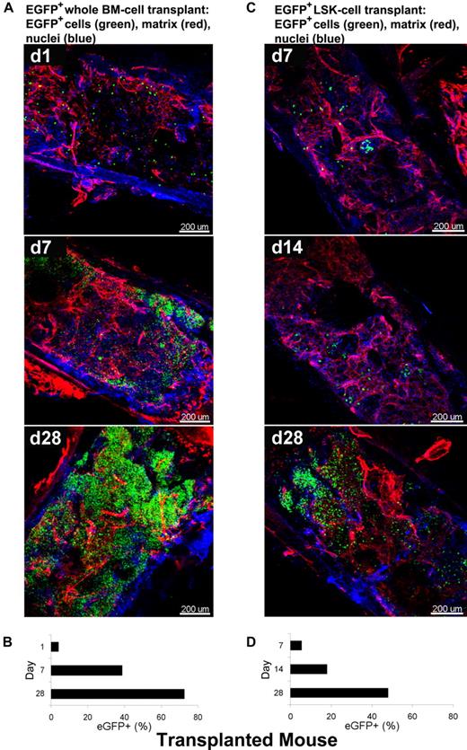
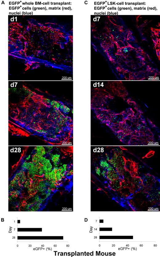
As a second model system in the mouse, we used a “treatment” protocol, the rescue of an irradiated animal by stem cell infusion. To visualize over time BM recovery after transplantation using whole-mounts, we used BM tissue from animals genetically engineered to express EGFP. Two types of BMT mice were generated as described: B6/tBM/EGFP and B6/LSK/EGFP mice. Figure 6 shows 3D images acquired by CLSM using BM whole-mount specimens. Extracellular matrix and nuclei were stained with RhoRX-anti-HSPG2 Ab (perlecan) and DAPI, respectively. In BM tissues of the B6/tBM/EGFP mice, EGFP+ donor cells were detected even on day 1 (4.6%). EGFP+ cells expanded focally and diffusely from the bone edge to the center of the bone cavity on day 7 (37%), with maximal numbers of donor cells present at day 28 (66%; Figure 6A and supplemental Video 7). In BM tissues of B6/LSK/EGFP mice, foci of EGFP+ cells were apparent in the inner parts of the tissue on day 7 (4.3%) and greatly increased in number by day 28 (47%) (Figure 6C). The lesser magnitude of EGFP+ cell expansion in B6/LSK/EGFP mice was attributable to the 1000-fold lower number of transplanted cells, compared with the B6/tBM/EGFP mice. Parallel flow cytometric analyses confirmed the quantitative increase of EGFP+ cells in good correlation with microscopic analysis (Figure 6B-D), from 4% on day 1 to 39% on day 7 (Figure 6B) in the B6/tBM/EGFP mice. On day 28, the proportion of EGFP+ cells reached 72% or 48% in the B6/tBM/EGFP or the B6/LSK/EGFP mice, respectively.
Dynamic analysis of infiltration/expansion of EGFP cells in transplanted mice. Total BM or LSK cells were obtained from B6/EGFP mice expressing EGFP in all tissues and infused into B6 mice irradiated lethally, generating B6/tBM/EGFP or B6/LSK/EGFP mice. BM whole-mount specimens were examined at different time points by confocal microscopy (A,C) and isolated EGFP + hematopoietic cells were quantified by flow cytometry (B,D). (A) BM images of the B6/BM/EGFP mice on days 1, 7, and 28 illustrate: on day 1, massive destruction of extracellular matrix (red) and very few EGFP + cells (green) close to the bone edge; on day 7, remodeling of the extracellular matrix and increased number of EGFP+ cells, in islands beneath the bone edge; and by day 28, a complex network of extracellular matrix (red) and numerous EGFP+ cells evenly distributed. (B) Frequencies of EGFP-expressing cells in BM cells of the B6/BM/EGFP mice on days 1, 7, and 28 by flow cytometry. (C) BM images of the B6/LSK/EGFP mice on days 7, 14, and 28: at day 7, scarce clusters of EGFP+ cells appeared centrally located; at day 14, several clusters of EGFP+ cells were localized both centrally and peripherally, toward the bone edge; and at day 28, islands of EGFP+ cells were visible in the center of the tissue. (D) Frequencies of EGFP-expressing cells in BM cells of the B6/LSK/EGFP mice on days 7, 14, and 28, measured by flow cytometry. Nuclei were stained with DAPI. Scale bars are in micrometers. Related images appear in supplemental Video 7.
Dynamic analysis of infiltration/expansion of EGFP cells in transplanted mice. Total BM or LSK cells were obtained from B6/EGFP mice expressing EGFP in all tissues and infused into B6 mice irradiated lethally, generating B6/tBM/EGFP or B6/LSK/EGFP mice. BM whole-mount specimens were examined at different time points by confocal microscopy (A,C) and isolated EGFP + hematopoietic cells were quantified by flow cytometry (B,D). (A) BM images of the B6/BM/EGFP mice on days 1, 7, and 28 illustrate: on day 1, massive destruction of extracellular matrix (red) and very few EGFP + cells (green) close to the bone edge; on day 7, remodeling of the extracellular matrix and increased number of EGFP+ cells, in islands beneath the bone edge; and by day 28, a complex network of extracellular matrix (red) and numerous EGFP+ cells evenly distributed. (B) Frequencies of EGFP-expressing cells in BM cells of the B6/BM/EGFP mice on days 1, 7, and 28 by flow cytometry. (C) BM images of the B6/LSK/EGFP mice on days 7, 14, and 28: at day 7, scarce clusters of EGFP+ cells appeared centrally located; at day 14, several clusters of EGFP+ cells were localized both centrally and peripherally, toward the bone edge; and at day 28, islands of EGFP+ cells were visible in the center of the tissue. (D) Frequencies of EGFP-expressing cells in BM cells of the B6/LSK/EGFP mice on days 7, 14, and 28, measured by flow cytometry. Nuclei were stained with DAPI. Scale bars are in micrometers. Related images appear in supplemental Video 7.
Normal human BM and BM of patients with hematologic diseases
Human normal BM whole-mount segments were stained using 5 different combinations of cell/component–specific antibodies with distributions similar to that observed in the murine tissue (supplemental Figure 1 and supplemental Table 5). The comparison of cell counts obtained from microscopy images with those obtained from flow cytometry revealed some discrepancies (supplemental Table 5) independent of using fresh or preserved samples. The most likely explanation for observed differences is that the samples used in flow cytometry are contaminated with peripheral blood and also differential removal of cells with varying adhesion properties during the mechanical aspiration procedure, as previously reported.21
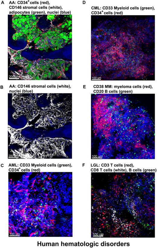
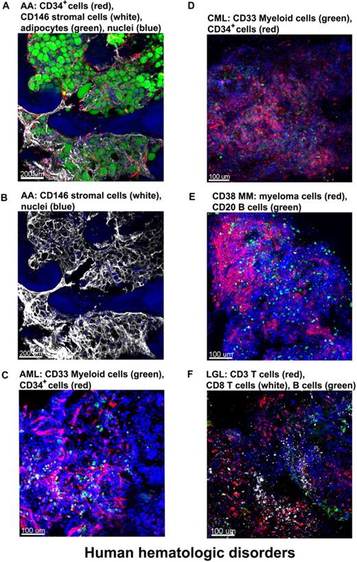
We obtained clinical samples from patients with hematologic diseases. BM from a patient with severe AA (SAA) was stained with antibodies for CD34 (CD34+ cells) and CD146 (stromal cells) and with BODIPY 493/503 for the lipid droplets of adipocytes.24 Confocal images (Figure 7A and supplemental Video 8) showed massive expansion of adipocytes surrounded by meshworks of CD146+ stromal cells and of vascular CD34+ endothelial cells. For a less obstructed view, the unmerged image highlights the stromal cell meshwork (Figure 7B).
Altered BM architecture in tissues from patients with hematologic diseases. BM whole-mount specimens from patients with hematopoietic disorders were fluorescently stained with cell lineage–specific antibodies and DAPI (nuclei). (A) SAA: most of the hematopoietic space is occupied by adipocytes (green) closely surrounded by almost overlapping vascular (CD34, red) and stromal (CD146, white) network. (B) Same image as in panel A but only the CD146+ staining to clearly display the stromal cell meshwork. (C) AML: both normal and malignant myeloid cells, recognized by anti-CD33 Ab, appear in clusters (green); in addition, an increased number of CD34+ cells (red) appear in close proximity to the endothelial matrix (red). (D) CML-blast crisis: CD34+ leukemic blasts (red) occupy the BM. (E) Multiple myeloma: massive numbers of irregularly shaped malignant CD38+ cells (red), forming a large nodule. (F) T large granular lymphocyte leukemia: sparsely distributed CD8+ cells (white), along with CD3+ cells (red) and sporadic CD20+ B cells (green). Scale bars are in micrometers. Related images appear in supplemental Videos 8 and 9.
Altered BM architecture in tissues from patients with hematologic diseases. BM whole-mount specimens from patients with hematopoietic disorders were fluorescently stained with cell lineage–specific antibodies and DAPI (nuclei). (A) SAA: most of the hematopoietic space is occupied by adipocytes (green) closely surrounded by almost overlapping vascular (CD34, red) and stromal (CD146, white) network. (B) Same image as in panel A but only the CD146+ staining to clearly display the stromal cell meshwork. (C) AML: both normal and malignant myeloid cells, recognized by anti-CD33 Ab, appear in clusters (green); in addition, an increased number of CD34+ cells (red) appear in close proximity to the endothelial matrix (red). (D) CML-blast crisis: CD34+ leukemic blasts (red) occupy the BM. (E) Multiple myeloma: massive numbers of irregularly shaped malignant CD38+ cells (red), forming a large nodule. (F) T large granular lymphocyte leukemia: sparsely distributed CD8+ cells (white), along with CD3+ cells (red) and sporadic CD20+ B cells (green). Scale bars are in micrometers. Related images appear in supplemental Videos 8 and 9.
Next, we examined various leukemic patients' BM whole-mount, stained specimens. A BM tissue of a pretreated acute myeloid leukemia (AML) patient was stained for myeloid cells (green, anti-CD33 Ab) and CD34+ cells/endothelial cells (red, anti-CD34 Ab) along with nuclei (Figure 7C). Both normal and malignant myeloid cells, recognized by anti-CD33 Ab, appear in clusters (green); in addition, an increased number of CD34+ cells (red) are present in close proximity to endothelial meshes (red). Figure 7D represents the image of BM from a chronic myeloid leukemia (CML) patient in blast crisis; an increased percentage of myeloblasts stained with the same antibodies as in the AML-BM tissue. CD34+ leukemic blasts were abundant and heavily infiltrated the BM. Figure 7E and supplemental Video 9 show the image of BM tissue from a multiple myeloma patient in which myeloma/normal plasma cells were visualized with fluorescently conjugated antibodies for CD38, B cells stained with antibodies for CD20, and nuclei with DAPI. Confocal images demonstrated massive proliferation of irregularly shaped malignant CD38+ cells (red) in the BM, forming large nodules. Figure 7F shows the BM tissue derived from a T large granular lymphocyte leukemia patient with sparsely distributed CD8+ cells (white), along with CD3+ cells (red), and the sporadic presence of CD 20+ B cells (green).
Quantitative measurement of cell distribution in BM compartments
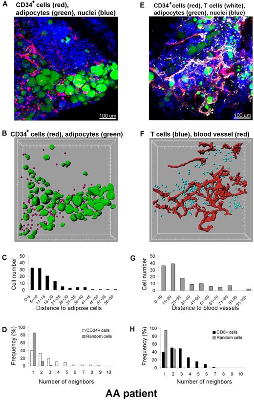
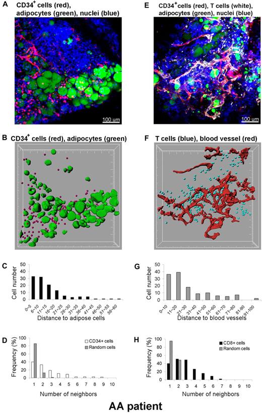
In addition to qualitative assessment of the 3D cell distribution, quantitative analysis was performed within the 3D space using the Imaris XT software integrating MATLAB applications. A BM whole-mount tissue volume of approximately 600 × 600 × 100 μm3 from a SAA patient was imaged by CLSM, and the 3D reconstruction (original image) is shown in Figure 8A. Qualitative inspection of the original images revealed an apparent close spatial association between CD34+ cells and adipocytes. To more precisely establish a relationship, we further investigated this observation. Cells were computationally segmented in 3 dimensions (Figure 8B segmented image), and these data were analyzed for the number and location of CD34+cells. Distances between CD34+ cells and adipocytes were calculated in 3D space (Figure 8C). Segmentation of cells of interest was performed using automatic intensity thresholding algorithms. CD34+ cells were detected using the “spots function” in Imaris software and displayed as spheres (red), and adipocytes were segmented using the isosurface function of the software. The calculated results (spots and isosurfaces) were manually edited for accuracy by 2 observers. The shortest distance (nearest neighbor) between spots (CD34+ cells) and adipose cells (isosurfaces) was determined using a distance transformation algorithm and “spots-to-surfaces distance” algorithms in the Imaris XT. CD34+ cells were classified based on this distance to adipose cells, and clustering was defined when cells were in contact or within a distance of less than 25 μm.25 Due to the size of most hematopoietic cells, a cell-to-cell threshold distance between 20 to 30 μm was judged appropriate. As illustrated in Figure 8C, more than 90% of CD34+ cells are within 25 μm from adipose cells. The clustering distribution was further confirmed with statistical analysis using the Mann-Whitney U test (SigmaStat software), by comparing the distances between CD34+ cells to adipocytes to those between nuclei of all cells to adipocytes. The difference in the median values between the 2 groups was greater than would be expected by chance (P < .001). In addition, to assess whether the observed clustering was real or reflected random distribution of the CD34+ cells, we further analyzed the data by neighboring distribution and in comparison with Monte Carlo simulation of randomly distributed cells of equal density (Figure 8D). Whereas randomly distributed cells had mostly 1 to 2 neighbors, CD34+ cells had many more neighbors, indicating cell clustering. In a similar manner, we analyzed the relationship between CD8+ cells observed in the apparent proximity of blood vessels (Figure 8E-H); indeed, the increased numbers of CD8+ cells found were a consequence of nonrandom distribution and were statistically significant. Consequently, CD34+ or CD8+ cells appeared to be located adjacent to adipocytes or to blood vessels, respectively, in the marrow of a SAA patient.
Quantitative analysis of cell distributions in 3 dimensions. A BM specimen from a patient with SAA was fluorescently labeled with antibodies to CD34, CD8, BODIPY 493/503 (adipocytes), and DAPI (nuclei) (A,E). Original confocal images are presented in top panels (A) CD34+ cells (red)/adipocytes (green) and (E) CD8+ cells (white)/blood vessels (red). Bottom panels display segmented images of (B) CD34+ cells (red)/adipocytes (green) and (F) CD8+ cells (blue)/blood vessels (red), computationally extracted from the original fluorescence images, to measure the distance to adipose cells (C) and blood vessels (G), respectively. Clustering of CD34+ cells (D) and of CD8+ cells (H) was analyzed by comparing experimental data (white columns in panel D) and (black columns in panel H) with a Monte Carlo simulation (hatched columns in panels D and H) of randomly distributed cells of same density in a similar volume. Representative images and results from one patient are presented. The analysis was repeated independently 2 to 4 times for 4 different specimens.
Quantitative analysis of cell distributions in 3 dimensions. A BM specimen from a patient with SAA was fluorescently labeled with antibodies to CD34, CD8, BODIPY 493/503 (adipocytes), and DAPI (nuclei) (A,E). Original confocal images are presented in top panels (A) CD34+ cells (red)/adipocytes (green) and (E) CD8+ cells (white)/blood vessels (red). Bottom panels display segmented images of (B) CD34+ cells (red)/adipocytes (green) and (F) CD8+ cells (blue)/blood vessels (red), computationally extracted from the original fluorescence images, to measure the distance to adipose cells (C) and blood vessels (G), respectively. Clustering of CD34+ cells (D) and of CD8+ cells (H) was analyzed by comparing experimental data (white columns in panel D) and (black columns in panel H) with a Monte Carlo simulation (hatched columns in panels D and H) of randomly distributed cells of same density in a similar volume. Representative images and results from one patient are presented. The analysis was repeated independently 2 to 4 times for 4 different specimens.
Discussion
The most direct approach to understanding the complex cellular events at the organ level is to simply visually examine the tissue. Previously, direct visualization of the BM's complex structure has been essentially limited to imaging tissue sections by conventional histology, electron microscopy, and immunofluorescence confocal microscopy.26-28 Decalcification of the bone used for routine tissue sectioning can have adverse effects on both tissue morphology and protein antigenicity. To overcome this limitation, rare attempts have been made toward cryosectioning through intact bone.29 However, generating overlapping sections to cover large areas of tissues is technically challenging and labor intensive, as is generating serial sections.11-14
We show here a new methodology to visualize the 3D architecture of the BM without the use of physical sectioning by applying immunofluorescence methods to whole-mount specimens and confocal microscopy optical sectioning. In addition, we report for the first time confocal reflection imaging to successfully visualize bone structures. This method is noninvasive, does not require fluorescent labeling, and allows penetration depths to at least 180 μm by confocal reflection of a 633-nm laser light. The technique should be a valuable tool for imaging bone, expanding previously described biologic applications.30-32 Reflection and fluorescence images can be combined to reveal immunolabeled structures and encasing bone. Very large regions of the intact tissue volume can be examined by generating tiled images. The unprecedented high resolution images from optical sections were used to computationally reconstruct the complete 3D patterns of great complexity to depths of approximately 150 μm, comprising approximately 10 to 15 layers of cells and vascular and bone structures. Furthermore, the 3D renderings can be rotated, readily allowing visual inspection at various angles of multiple cell distributions in situ in normal and diseased tissue. Our reconstructions can be used for effective 3D morphometric noninvasive analyses that may serve as basis for obtaining realistic, spatially resolved microanatomical structures.
We developed an immunolabeling technique with increased resolution, range of applicability, and ease of use. Unlike conventional tissue sectioning, this method involved no bone decalcification, paraffin embedding, nor bone sectioning. Bone marrow tissue was generally fixed only lightly. Thus, antigenicity of target molecules was retained and there was a high degree of structural preservation. The general immunocytochemistry principles applied to whole mounts do not differ substantially from those used for cell suspensions or tissue sections. However, foremost to consider is the problem of tissue penetration by reagents.33,34 Our experience using labeling through the cut-open face of the BM tissue is that reagents can penetrate much deeper (∼ 250 μm), and the limiting factor is then the ability to collect emitted light from such depths (our unpublished observations, May 2009). Notably, we were able to perform successful multilabeling (up to 3 cell types simultaneously stained), but the concentration of various antibodies was higher and time of incubation was often extended for several days compared with those parameters conventionally used for tissue sections. Because it is the general experience that smaller molecules penetrate well, we have used F(ab)2 fluorescently labeled secondary antibodies instead of whole immunoglobulin G. The second obstacle in whole-mount immunocytochemistry derives from nonspecific binding and high background due to the thickness of the specimen.34 The use of appropriate blocking reagents before antibody labeling reduces nonspecific labeling. To our surprise and advantage, BM exhibits very low autofluorescence (and therefore background) compared with lymphoid tissues such as lymph nodes, thymus, and spleen. This optical property of the BM tissue allows reaching imaging depths of approximately 150 μm, rarely achievable by confocal microscopy.
The application of immunofluorescence to whole-mounts can be a powerful and robust noninvasive means for obtaining detailed information within the 3D context of the marrow. Even during this exploratory study, several unanticipated feature were revealed. There was an intricate architecture of stroma and the elaborate network of extracellular matrix surrounding hematopoietic cells, encased in bone fossae in normal mouse tissue. B cells appeared in nests, encircled by the arterioles and venules that supply and drain intratrabecular spaces. BM from an untreated SAA patient showed a complex network of stromal cells surrounding abundant adipocytes. These results suggest potential unappreciated pathophysiologic roles for these “background” supporting cells in normal and failed hematopoiesis.
We exploited the ability to examine large regions of tissue for the pattern and distribution over time of even scarce cell populations. Two types of mouse models enabled us to visualize the process of BM destruction and recovery. Images from an AA model mouse exhibited drastic alterations in BM tissues, the process of adipose cell expansion, and immune destruction of recipient marrow. Images derived from transplanted mice revealed that EGFP+ cells predominantly localized in close proximity to the bone and in cluster formations, compatible with inferences from recently published experimental systems.7,10,35 Furthermore, in both the mouse AA model and in human AA, a marked increase in adipocyte number and size was unexpectedly observed, suggesting active proliferation of these cells. Especially in tissue from human AA patients, adipocytes and CD34+ cells tended to colocalize. A recent report has suggested that BM adipocytes are negative regulators of the hematopoietic microenvironment,36 and our results are compatible with an active role of adipocytes in the pathology of BM failure.
Quantitative analysis of cell interaction through a noninvasive technique was feasible. We describe a protocol for the measurements of cell-cell and cell–blood vessel interactions that uses automated, user-interactive image analysis methods based on a commercially available software package, Imaris XT, that integrates MATLAB-run open source algorithms into 3D visualization software. Because the source code is freely available, macros can be customized by investigators to various applications. The advantages of this approach are robustness in segmentation and quantitative analysis, which combined with 3D rendering, provides powerful visual and mathematical analysis. Using this analysis, we demonstrated clustering of CD34+ and CD8+ cells around adipocytes and blood vessels, respectively, in a human BM biopsy from a patient with SAA. We further showed that clustering was statistically significant and occurred nonrandomly. Although the exact implication of the clustering remains to be further elucidated, it provides a powerful tool of comparative analysis. The possibility to perform quantitative analyses may be applied in broader experimental circumstances (ie, mouse leukemia, to mark cell populations, and to other human diseases). Furthermore, it enables future pathologic classification based on 3D images for visual assessment of drug effects.
The online version of this article contains a data supplement.
The publication costs of this article were defrayed in part by page charge payment. Therefore, and solely to indicate this fact, this article is hereby marked “advertisement” in accordance with 18 USC section 1734.
Acknowledgments
We thank Dr Christian A. Combs (National Heart, Lung and Blood Institute [NHLBI], NIH) for discussions and advice throughout this study, Dr Bernd Zinselmeyer (National Institute of Neurological Disorders and Stroke [NINDS], NIH) for discussions and assistance with the cell cluster analysis, Kevin Frischmann (Bitplane) for assistance with the quantitative cell distance measurements, Dr Pamela Gehron Robey (National Institute of Dental and Craniofacial Research [NIDCR], NIH) for helpful discussions, Dr Katherine Calvo (Clinical Center, NIH), Dr Zu-Xi Yu (Pathology Core, NHLBI) for assistance with immunohistochemistry, Dr Motoyuki Nakao (NHLBI, NIH) for assistance assembling figures, Keyvan Keyvanfar (NHLBI, NIH) for assistance with flow cytometric analysis, and the anonymous reviewers for thoughtful and stimulating comments.
This work was supported by the NIH Intramural Research Program.
National Institutes of Health
Authorship
Contribution: T.T. and D.M. conceived and designed the experiments, performed the experiments, analyzed the data, contributed reagents/materials/analysis tools, and wrote the manuscript; J.C. contributed to material and analysis tools, performed flow cytometric experiments, and edited the manuscript; R.T.C. contributed to material and analysis tools; S.K. contributed to writing the manuscript; and N.S.Y. conceived and designed the experiments, analyzed the results, and contributed to writing the manuscript.
Conflict-of-interest disclosure: The authors declare no competing financial interests.
Correspondence: Tomoiku Takaku, MD, PhD, Hematology Branch, NHLBI/NIH, Bldg 10-CRC, Rm 3E-5216, 9000 Rockville Pike, Bethesda, MD 20892; e-mail: takakut@nhlbi.nih.gov.

